
Welcome to part 4 of the “Maximizing BLE Throughput” blog post series! This blog post will provide the key takeaways from our previous 3 posts and also bring us up-to-date with the latest BLE spec (such as 2M PHY).
Update: Please check out our other blog posts in the Maximizing BLE Throughput series. You can find a lot of great information to better understand how BLE works and what factors affect transfer speed, DLE, etc. But be aware that some of the information in these posts may be outdated.
Bluetooth Low Energy was originally intended to transfer small chunks of data back and forth between devices. However, it’s now commonly used to transfer large amounts of data such as firmware updates, continuous sensor data, and even audio. For these types of use cases, it can become necessary to optimize your apps to maximize throughput. This article will explain the most important techniques to improve throughput.
Before we begin, let’s cover some of the basic BLE terminology:
During a connection interval, the master and peripheral exchange packets as shown below:

Multiple packets can also be exchanged in a connection interval as shown below:

This process can continue until both sides no longer have additional data to send, a package fails to get delivered, or if the maximum connection event duration is reached.
The more packets you can send in a connection, the higher your throughput will be. The maximum packets you can send in an interval is often limited by the maximum connection event duration.
Let’s look at the Bluetooth layers that the application data travels through and discuss the layers that can be optimized for improving throughput.
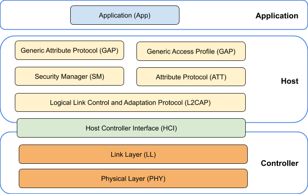
The BLE layers are organized in three major building blocks: Application, Host, and Controller. As the name suggests, the Application block contains the user application, which interfaces with the Bluetooth protocol stack. The Host covers the upper layers (GAP, L2CAP etc) of the BLE protocol stack, while the Controller covers the lower layers (LL, PHY).

Generic Attribute Profile (GATT): GATT is the layer developers often interface with the most and are accustomed to. GATT defines the protocol of transferring data between two BLE devices. Application data is uniquely identified through a small entity known as an Attribute. A group of Attributes form Characteristics, which adds additional properties such as permission and rules of interaction for a unique set of data. A group of Characteristics form an entity known as Service which adds a larger blueprint for a given feature or functionality. For example, Battery Service includes a Battery Level Characteristic that includes the battery level of a given device.
Generic Access Profile (GAP): GAP controls connections and advertising in Bluetooth. It’s what makes your device communicate with the outside world.
Security Manager (SM): The SM defines the methods and protocols for pairing and key distribution.
Attribute Protocol (ATT): ATT defines the protocol of transferring the attribute data. This includes GATT related functionality, such as Write Request, Write Response, Notification, Read Response, etc. In short, GATT defines and creates appropriate attributes for a given application, and ATT creates outgoing and parses incoming packets that define the action in the GATT layer.
Logical Link Control and Adaptation Protocol (L2CAP): L2CAP is responsible for Quality of Service (QoS), routing, fragmentation, and reassembly of packets for higher layer protocols such as ATT, Security Management Protocol (SMP), etc.
Host Controller Interface (HCI): The HCI interfaces the Host with the Controller through a standardized interface.
Link Layer (LL): LL interfaces with the Physical Layer (Radio) and provides the higher levels an abstraction and a way to interact with the radio. This layer handles the transfer of L2CAP packets while ensuring guaranteed delivery and integrity of data.
Physical layer (PHY): The PHY layer is at the bottom layer of the BLE stack and is responsible for actually transmitting and receiving information over the air via radio waves on the ISM band (2.4 GHz).
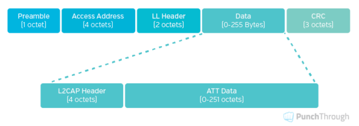
A BLE packet containing application and transferred over the air has the following structure:

Note: The Data field is dependent on the Bluetooth specification. In Bluetooth v4.0 and 4.1, the maximum size of the Data field was 27 bytes. With Bluetooth v4.2, a new feature was added to negotiate the Data field length with Data Length Extension.
The Data field of a BLE Packet is filled with L2CAP messages as shown below:

The takeaway is that we strive to transfer LL packets with their payload data field maximized (23 bytes of ATT PDU without DLE or up to the max negotiated for DLE).
The connection interval is how often the devices talk to each other. Normally, we may assume that the more often two devices talk, the higher the throughput will be. However, this may not always be true. Depending on the size of the packets being sent, in some cases increasing the connection interval may actually yield faster throughput. This is because with a longer interval, we could transfer more packets.
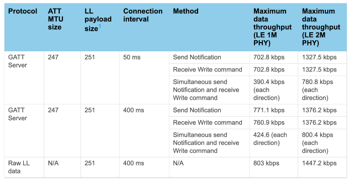
This can be observed in the tests mentioned in Table 2 of Nordic’s S140 softdevice specification:

As we can see, a connection interval of 400ms results in a higher throughput than 50ms. This is due to how the packet length is not an exact fraction of 50 or 400.
This doesn’t match phone to a nordic in which the phone is deciding the connection event duration
It should be noted that this test setup has ideal conditions with two NRF52s. This does not match when a phone is talking to a Nordic device and deciding the connection event duration. This test also does not consider the scenario where a packet is dropped. If a packet is dropped in the beginning of a 400ms connection event, you would need to wait until the next connection even to send new packets. So, in this way, a shorter connection interval may actually be better.
The connection interval can range from 7.5ms up to 4s. The lowest connection interval that you could use depends on the capabilities of the device. Android devices can support a connection interval as low as 7.5 ms, whereas iOS devices can go down to 15ms. From our experience, throughput gains are made as the connection interval is reduced down to 15 ms. Going below that doesn’t necessarily yield faster throughput.
A peripheral can request for the connection interval to be lowered using a Connection Parameters Update Request message. Some devices may initially connect at a longer connection interval before lowering it when requested.
Throughput depends on the method used to transfer data. Whenever possible, use Write Command instead of Write Request when sending data from GATT Client to GATT Server. When sending from GATT Server to GATT Client, use Notification instead of Indication.
Write Commands and Notifications are asynchronous, allowing either to be sent back-to-back within single connection events. On the other hand, Write Requests and Indications are synchronous — they require responses before the next ATT command can be sent. Because the receiver usually can’t prepare the response in under 150us (the time delay between consecutive packets, aka Inter Frame Space), the response needs to wait until the next connection event. This reduces the throughput.
Check out Table 1 in Nordic’s s140 softdevice specification to see how different transfer methods affect throughput. It should be noted that this is an ideal situation with two NRF52 devices and it isn’t representative of how a phone’s OS manages a connection as the Central device.
The ATT Maximum Transmission Unit (MTU) is the maximum length of an ATT packet. Per the Bluetooth Core Specification, the maximum length of an attribute can be 512 bytes. In reality, it can be slightly larger than this to accommodate the ATT header. On Android, the maximum MTU can be 517 bytes. The implementation of the Bluetooth stack is the key factor that determines the ATT MTU on both client and peripheral.
A generic ATT packet has the following structure:

Where OP-Code indicates the ATT Operation such as Write Command, Notification, Read Response,etc. The ATT Data field contains the application data.
So, how much overhead do we have when sending data?
Let’s suppose the ATT MTU is 23 bytes. In this code, the overhead would be 3/23 = 13%. If the MTU size is 512, the overhead would be 3/512 = 0.6%. So, if we use a larger MTU size, the overhead in each transmission would be lower.
The throughput can be increased up to 15% with a larger MTU (see our test results in Maximizing BLE throughput: Use larger ATT MTU). Using a larger MTU also has the benefit of slightly reducing power consumption, as we can send more data in fewer transmissions.
With Bluetooth 4.2, Data Length Extension (DLE) was introduced. With DLE, the Data Channel Protocol Data Unit (PDU) payload could be increased from 27 up to 251 bytes as shown below:

DLE allows more data to be sent in a packet. This results in less packet overhead, fewer empty packets, and fewer inter-frame spaces (see Maximizing BLE Throughput Part 3: Data Length Extension (DLE)). Keep in mind that because of the larger packet length, fewer packets fit into a single connection event. So, if DLE increases data payload size by 10x, you won’t see 10x improvement in throughput.
Using DLE results in less overhead per transmission, which means less time spent actively transmitting and receiving — therefore, lower power consumption. So, using DLE provides both faster throughput and longer battery life.
The maximum achievable throughput values depends upon many different factors: hardware/chipset, PHY layer used, stack version, OS version, direction of data, how busy the master or slave devices are with other connections and tasks, wireless environment, etc. Based on our own testing ~50 KB/s data throughput is achievable on newer Android and iOS devices with DLE enabled on the default LE 1M PHY.
We recommend to generally use the maximum packet length available for DLE.
Bluetooth 5.0 introduced a new PHY configuration — 2 Megabit PHY (aka 2M PHY). This configuration increases the symbol rate to 2 Mega symbols per second, where each symbol corresponds to a single bit. This doubles the number of bits sent during a given period compared to regular 1M PHY.
It should be noted that doubling the symbol rate does not necessarily double the throughput. The PHY layer is at the bottom of the BLE stack, and application data needs to traverse the entire stack before it gets transmitted. So, there can be a number of other factors that affect the overall throughput. As can be seen in Nordic’s S140 softdevice specification, throughput is only increased by about 33% from using 2M PHY (without DLE).
When combined with DLE, however, we see throughput can be increased by almost 90%. This is because DLE reduces the overhead per transmission (as we discussed earlier). But we still don’t see a 2x improvement because the inter-frame spacing has a significant impact on throughput.
Another benefit of using 2M PHY worth noting is that it helps reduce power consumption. This is because for a given amount of data, 2M PHY allows us to reduce the transmit time (thereby reducing energy consumption).